Intro to ProtoPie Connect 3 of 7: Arduino Part 1 - Connecting with Blokdots
Learn how to use Blokdots to integrate with your Arduino projects without writing any code.


Introduction
Increasingly, our digital experiences are extending beyond computers and mobile screens. Say you want to introduce physical controls in your design… a button… a knob you can turn… a bar that you can touch and slide your finger across. Inexpensive computing boards like the Arduino Uno are making this increasingly accessible to those wishing to experiment.
In this tutorial we’ll work with a climate control prototype that can be operated by either a touch screen or with physical with physical knobs that can be turned and clicked. These are known as rotary encoders, and even if you haven’t heard the term, you’ve no doubt interacted with one at some point. These have a clicking sensation you can feel as you twist the knobs. The clicks you feel as you turn the knob increase or decrease something by one step with each click — say the volume control on your car’s audio system
What you'll learn
In this tutorial we’ll cover the following:
- What is Blokdots?
- Wiring up your Arduino circuit
- Programming your Arduino with Blokdots
- Using Blokdots to send message to your Pie via ProtoPie Connect
Time to complete: 30-60 minutes
This depends on your experience with wiring up an Arduino circuit.
Blokdots
Normally when working with Arduino, a little bit of coding is involved. If the thought of writing any code at all is enough to make you run for the hills, there is an alternative. Blokdots is a program that runs on your computer allowing you to program your Arduino without the need to write any code at all. The best news? It comes built in with an integration with ProtoPie Connect, meaning you can very quickly start having your Pies react to interaction with physical devices.

At the time of this writing, Blokdots is still in beta, but it’s already proving just how fast and easy it is to work with physical devices.
Parts you’ll need
All of the lessons up to this point have not required any additional purchases above a ProtoPie license. To follow along with this tutorial you’ll need to source a number of parts:
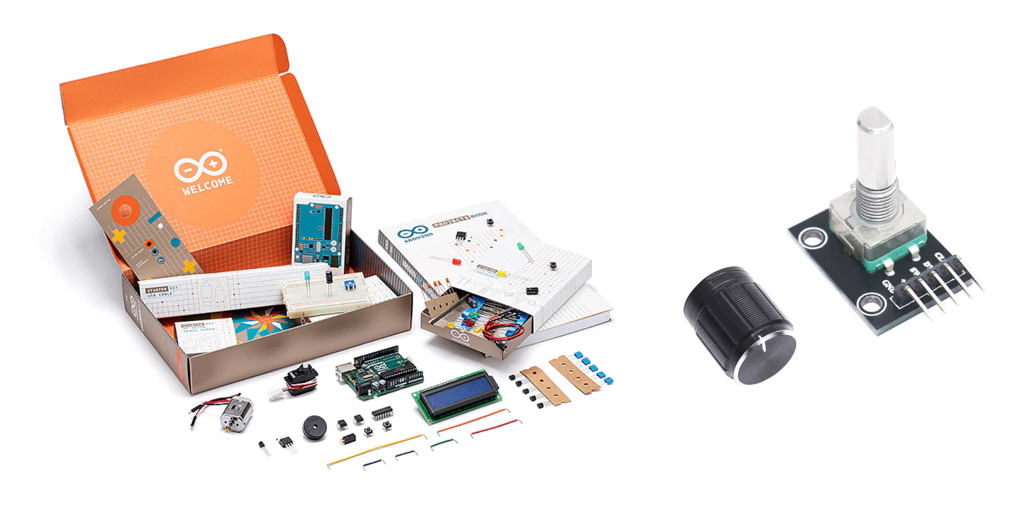
TL;DR — I’m a n00b. Make this easy.
.png?fm=webp)
Just buy the Official Arduino Starter Kit, which will come with almost everything you need for this project, plus a pack of these rotary encoders.
Wire it up!
While Blokdots takes care of the coding side of things, you still need to get your hands dirty wiring things together. For simple things, this isn’t hard, and it’s very likely you can find a circuit diagram online somewhere that will show you exactly how to connect your components to the Arduino board without needing to understand exactly how it works.
Follow the diagram below to wire up your Arduino circuit.
💡 If you need a little more hand-holding, there are detailed instructions below the video.
.png?fm=webp)
Let's do this!
Visit Blokdots.com and click the yellow download button in the top right. As Blokdots is still in beta, updates are frequently being released with new features and fixes. Be sure to check for updates often.
Second, we’ll be working with a Pie file in its completed state. Download it here:
https://cloud.protopie.io/p/35d69ddd96
Now follow along with the video below:
Things to try
- The Pie has a counter-clockwise rotation when increasing the fan speed, yet when we use the physical controls, we turn the encoder clockwise. See if you can figure out how to make the fan speed control knob work opposite to the temperature control — having it turn counter-clockwise to increase the fan speed, and clockwise to decrease it.
- You have a second button wired up, but thus far unused. What might you do with it?
Help! How do I wire my circuit?!
If you're not familiar with wiring circuits, fear not! The following are descriptions of all of the components involved in the circuit, and detailed instructions of how to wire everything up.
Getting to know your Arduino

The Arduino is designed to make connecting components easy.
- There are a group of connectors along the top — these are the digital connectors, and they are clearly numbered. We’ll be using several of these to connect our encoders.
- There is a group of connectors along the bottom labeled “POWER.” We’ll be using the connectors labeled “5V” and “GND.”
Breadboard explained
We’ll be using something called a “Breadboard” to connect everything. A breadboard makes it easy to connect your electronic components without needing to solder them together.
The Arduino Starter Kit comes with a breadboard very similar to the one in the image below. It is made up of a grid of holes:

It’s important to understand that certain groups of holes are connected. There are two rows of holes at the top, and another two rows at the bottom. They are labeled with + and – at either end. The holes in each of these four rows are connected together. Typically you’ll use these rows to connect power to your project. If you connect a power source to ANY of the holes in the very top row, anything else plugged into the top row will be powered by it.
The groups of holes in the middle are arranged in vertical groups of 5. Each of those groups of 5 is also connected together. You plug you components into these groups, and we use pieces of wire to make connections between groups of 5 and power rows.

Rotary encoders
A rotary encoder is a special kind of knob that clicks as you turn. The ones used in this project are also push buttons.

There are 5 connector pins, all clearly labelled:

From left to right:
- GND - Ground pin. This connects to the Arduino’s GND connector
- + - Voltage pin. This connects to Arduino’s 5V connector
- SW - this is the pin that specifically signals when the knob’s pushbutton has been pressed. This will connect to one of Arduino’s Digital connectors
- DT - the encoder’s Data pin. Connects to one of Arduino’s digital connectors
- CLK - the encoder’s Clock pin. Connects to one of Arduino’s digital connectors
💡 It’s not important that you understand how DT and CLK actually work. What IS important is that when you use encoders with Blokdots, the DT and CLK pins need to be connected to sequential digital connectors on the Arduino. For example, if the DT pin is connected to Digital 3, then the CLK pin needs to be connected to Digital 4. We’ll cover this again when we get to wiring everything up.
The pins of the encoder conveniently fit into the breadboard!

Go ahead and push both encoders into the breadboard. Plug them in so that each pin of the encoder is connected to a different vertical group of five holes.

Jumper wire
The last piece of the puzzle is the wire that connects everything together. The Arduino Starter Kit comes with a number of lengths of jumper wire. The color you use doesn’t matter — wire is wire — however the colors help to identify different parts of your project. For example, a red wire is commonly used to indicate power (or more specifically voltage). Feel free to use whatever color scheme makes sense to you.

Follow the diagram
Remember the wiring diagram from above? Connect wires to match what you see in the diagram. Remember, the colors of the wire you use don’t matter, so if you don’t have the same colors as shown below, simply use another color.
Provide power to the breadboard:
- Connect a wire from Arduino’s 5V connector to ANY of the holes on the bottom row (marked with “+”). This row is the power strip.
- Connect a wire from either of Arduino’s GND connectors to ANY of the holes on the second from the bottom row (marked with “–”). This row is the ground strip.
Be mindful that if you have your project oriented the same is in the diagram, the encoders are facing away from you right now, so from this perspective, the pins from left to right are as ordered as follows:
- CLK
- DT
- SW
- +
- GND
Wire up encoder 1:
- Connect a wire between ANY of the holes in the ground strip to ANY of the holes in the group of 5 that the encoder’s GND pin is connected to.
- Connect a wire between ANY of the holes in the power strip to ANY of the holes in the group of 5 that the encoder’s + pin is connected to.
- Connect a wire between Arduino’s Digital 2 connector and ANY of the holes in the group of 5 that the encoder’s SW pin is connected to.
- Connect a wire between Arduino’s Digital 3 connector and ANY of the holes in the group of 5 that the encoder’s DT pin is connected to.
- Remember when I mentioned that Blokdots requires the encoders to use sequential connectors? Since the DT pin is connected to Digital 3, the CLK pin needs to connect to Digital 4. Connect a wire between Arduino’s Digital 4 connector and ANY of the holes in the group of 5 that the encoder’s CLK pin is connected to.
Wire up encoder 2:
- Connect a wire between ANY of the holes in the ground strip to ANY of the holes in the group of 5 that the encoder’s GND pin is connected to.
- Connect a wire between ANY of the holes in the power strip to ANY of the holes in the group of 5 that the encoder’s + pin is connected to.
- Connect a wire between Arduino’s Digital 5 connector and ANY of the holes in the group of 5 that the encoder’s SW pin is connected to.
- Connect a wire between Arduino’s Digital 6 connector and ANY of the holes in the group of 5 that the encoder’s DT pin is connected to.
- Like before, we need to connect the CLK pin to the next sequential digital connector on the Arduino. Connect a wire between Arduino’s Digital 7 connector and ANY of the holes in the group of 5 that the encoder’s CLK pin is connected to.
If you did everything right, it should look similar to this:

Good job! You've just connected your first Arduino project with Blokdots using ProtoPie Connect. Let's see what else we can do with this in Intro to ProtoPie Connect 4 of 7: Arduino Part 2 - Roll Your Own Sketch Code.


